

Call Support 24x7
+91 7559349467
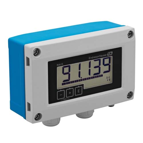
Tronsoft Technologies offers industrial instrumentation solutions designed to support reliable process monitoring and measurement. Loop Powered Process Indicators provide a convenient way to view process values transmitted by compatible field instruments through a current loop. They help operators monitor important operating parameters directly at the measurement point without always needing to refer to a remote control panel.
Designed for industrial process monitoring applications, loop powered indicators can be used with compatible transmitters to display variables such as pressure, temperature, flow, and level. Their suitability depends on the input signal, measurement range, installation requirements, and the specifications of the selected instrument.
A loop powered process indicator is an electronic display instrument connected to a compatible current loop, commonly using a 4–20 mA signal. It displays the process value represented by the incoming signal, helping operators understand the current operating condition of a system.
Unlike indicators that require a separate power connection, loop powered models obtain operating power from the current loop, subject to the device's electrical requirements and available loop voltage. This can simplify installation where a suitable signal loop is already available.
Loop powered process indicators are useful in industrial facilities where local visibility of measurements can support routine monitoring, inspection, and troubleshooting.
Compatible models can receive standard 4–20 mA analogue signals from industrial transmitters. Always confirm the supported input signal and electrical requirements before installation.
A local display allows personnel to check a process measurement near the instrument. Depending on the selected model, display formats may include numeric readings and configurable engineering units.
Loop-powered operation can reduce the need for a separate power supply at the indicator location. The transmitter, indicator, and control system must be compatible with the electrical requirements of the complete loop.
Depending on the model, the display may be configured to represent the incoming signal across a specified process range. Correct scaling helps ensure that the displayed value corresponds to the actual measurement range.
Depending on the product configuration, indicators may be suitable for field or panel installation. Mounting method, enclosure protection, environmental conditions, and hazardous-area requirements should be verified for the selected model.
Loop powered process indicators can support local monitoring across a range of industrial applications.
Pressure measurement: Display pressure values received from compatible pressure transmitters.
Temperature monitoring: Show temperature values supplied by compatible temperature measurement systems.
Flow measurement: Provide a local display of flow transmitter signals when the input and scaling are supported.
Level monitoring: Display level values derived from compatible level transmitters.
Water and wastewater treatment: Support local observation of instrument readings at suitable measurement points.
Process manufacturing: Help operators monitor selected process parameters during routine operation.
Pumping systems: Provide a convenient local indication of compatible instrument measurements.
Utilities and industrial plants: Support inspection and troubleshooting where accessible process readings are beneficial.
The final application suitability depends on the instrument's input specifications, installation environment, and operating conditions.
A loop powered process indicator displays the process variable represented by an incoming current signal. A typical installation follows these steps:
Measurement: A compatible transmitter measures a process variable such as pressure, flow, temperature, or level.
Signal transmission: The transmitter communicates the measurement through a current loop, commonly using a 4–20 mA signal.
Signal reception: The indicator receives the current signal within its supported electrical limits.
Signal conversion and scaling: The instrument interprets the input and converts it into the configured display value.
Local indication: The displayed reading enables personnel to view the process value near the installation point.
Correct wiring, configuration, signal scaling, and loop voltage are important for reliable operation. Follow the selected model's technical documentation during installation and commissioning.
The exact technical specifications should be confirmed against the datasheet for the model supplied by Tronsoft Technologies.
| Parameter | Specification to Confirm |
|---|---|
| Input signal | Whether 4–20 mA or other signal formats are supported |
| Power supply | Loop-powered operation and required loop voltage |
| Display type | LCD, LED, or other supported display |
| Display range | Minimum and maximum configurable readings |
| Accuracy | Model-specific accuracy and measurement error |
| Mounting | Field-mounted, panel-mounted, or other configuration |
| Enclosure protection | Applicable IP or other protection rating |
| Operating temperature | Manufacturer-specified ambient temperature range |
| Output or alarm functions | Availability of optional outputs or alarms |
| Certifications | Applicable approvals for the selected model, if any |
A loop-powered design can reduce wiring and power-supply requirements when the instrument is compatible with an existing current loop.
Operators can check measurements near the process equipment without relying exclusively on a central monitoring screen.
Local indication can help personnel compare readings, observe operating conditions, and identify values that may require further investigation.
Compatible indicators can be incorporated into suitable measurement loops containing transmitters and associated control equipment, subject to the electrical design of the installation.
A visible process reading can help maintenance personnel investigate measurement discrepancies and assess operating conditions. It should be used alongside appropriate calibration and diagnostic procedures.
Before choosing a loop powered process indicator, consider the following factors:
Input signal: Verify that the indicator supports the transmitter's output signal.
Measurement range: Confirm the process range and the required display scaling.
Loop voltage: Check that sufficient voltage remains available for the transmitter, indicator, and other connected devices.
Display readability: Select a display suitable for the viewing distance and lighting conditions.
Installation method: Determine whether field mounting or panel mounting is required.
Environmental conditions: Review temperature, moisture, dust, vibration, and enclosure protection requirements.
Additional functions: Confirm whether configurable units, backlighting, alarms, or communication features are necessary.
Compliance requirements: Check the relevant approvals when the installation has specific safety or hazardous-area requirements.
Reviewing these points before procurement helps ensure that the selected indicator is suitable for the intended process application.
Tronsoft Technologies provides industrial instrumentation and automation solutions for process monitoring and control applications. Selecting the appropriate process indicator requires more than matching a product name; signal compatibility, loop design, installation conditions, and display requirements must also be considered.
When evaluating a loop powered process indicator for your facility, discuss the application, connected transmitter, required measurement range, and mounting environment with the Tronsoft Technologies team. These details help establish the appropriate product configuration for your project.
Contact Tronsoft Technologies to enquire about product availability, technical documentation, and application suitability.
1. What is the main purpose of a loop powered process indicator?
Its primary purpose is to display a process value represented by a compatible transmitter signal, allowing personnel to view measurements locally at the installation point.
2. How does a loop powered process indicator receive power?
It draws operating power from the current loop rather than requiring a separate supply at the indicator, provided the loop voltage and device requirements are satisfied.
3. Can a loop powered process indicator work with a 4–20 mA transmitter?
Yes, if the indicator supports the transmitter's 4–20 mA output and the complete loop meets the required electrical and configuration specifications.
4. Which process variables can these indicators display?
Depending on the transmitter and configuration, they may display pressure, temperature, flow, level, and other variables represented by a compatible input signal.
5. Does a loop powered process indicator require a separate power supply?
Typically, no separate supply is required for a loop-powered model. However, the complete loop must provide sufficient voltage for all connected devices.
6. What should I check before purchasing a process indicator?
Check the input signal, loop voltage requirements, display range, accuracy, mounting arrangement, environmental protection, and any required approvals.
7. Where are loop powered process indicators used?
They are used in suitable industrial applications such as manufacturing, water treatment, pumping systems, utilities, and process plants where local measurement displays are helpful.
8. How can I enquire about loop powered process indicators from Tronsoft Technologies?
Contact Tronsoft Technologies with your application details, transmitter signal, measurement range, and mounting requirements to discuss product suitability and available technical specifications.
Contact Us
Feel Free To Get In Touch With Us
Office Address:
Karve road, near Garware metro stn, Pune | 411030 India
Follow Us:-
Looking For More?
Call Support 24x7
+91 7559349467